
A namespace wraps a global system resource in an abstraction that makes it appear to the processes within the namespace that they have their own isolated instance of the global resource. Changes to the global resource are visible to other processes that are members of the namespace, but are invisible to other processes. One use of namespaces is to implement containers.
This page provides pointers to information on the various namespace types, describes the associated
/procfiles, and summarizes the APIs for working with namespaces.
The quote above is how the Linux manpage describes namespaces. In short, namespaces are a powerful tool for resource isolation, essential for containerization, hardening system security, and managing resources efficiently.
Namespace Types
The following table shows the namespace types available on Linux. The second column of the table shows the flag value that is used to specify the namespace type in various APIs. The third column identifies the manual page that provides details on the namespace type. The last column is a summary of the resources that are isolated by the namespace type.Namespace Isolates Description Cgroup Cgroup root directory Control Groups allow independent control of resource usage (CPU, memory, etc.), enabling resource limits and priority allocation IPC System V IPC, POSIX message queues Isolates inter-process communication resources so that communication stays independent across namespaces, avoiding interference Network Network devices, stacks, ports, etc. Provides an independent network environment, including isolation of IP addresses, network devices, and ports Mount Mount points Supports independent filesystem mount configuration; each namespace can have its own view of the filesystem PID Process IDs Enables independent management of process IDs; PIDs inside a namespace are isolated from the outside and PID values can be reused Time Boot and monotonic clocks Allows independent system time and monotonic clocks, useful for scenarios requiring separate clock management User User and group IDs Lets user and group IDs be redefined within a namespace, improving security isolation and permission management flexibility UTS Hostname and NIS domain name Allows an independent hostname and NIS domain name, simulating the identity of a standalone system instance
Network Namespace
A Linux network namespace is part of the Linux kernel used to isolate the network stack, allowing each namespace to have its own independent network configuration: network interfaces, IP addresses, routing tables, firewall rules (iptables), and so on. These isolated environments let containers, virtual machines, or standalone processes have completely independent network configurations.
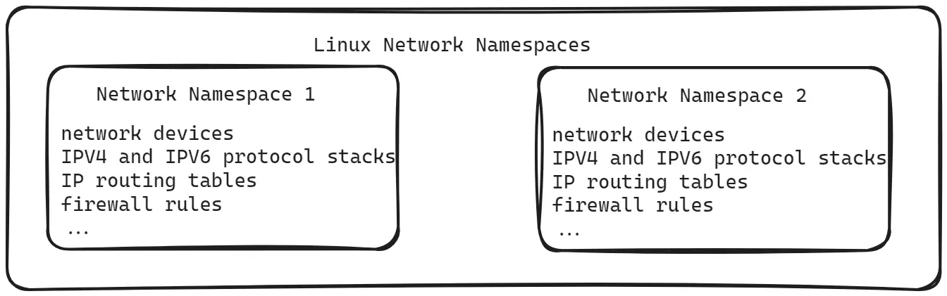
On a Linux system, when no network namespace is specified, you are operating in the so-called root network namespace. It is the first network namespace, created automatically at boot.
Query Network Configuration Information
Below are some commands for querying network configuration:
- ip link: show and manipulate network devices.
- arp: show and manipulate the ARP cache table.
- route: show or manipulate the network routing table.
Ip Link
The ip link command shows and manipulates network devices. It can add, delete, or change the state of network interfaces.
- Show interface status:
ip link show - Bring an interface up:
ip link set eth0 up - Bring an interface down:
ip link set eth0 down
ip link show1: lo: <LOOPBACK,UP,LOWER_UP> mtu 65536 qdisc noqueue state UNKNOWN mode DEFAULT group default qlen 1000 link/loopback 00:00:00:00:00:00 brd 00:00:00:00:00:002: eth0: <BROADCAST,MULTICAST,UP,LOWER_UP> mtu 9000 qdisc mq state UP mode DEFAULT group default qlen 1000 link/ether 00:15:5d:05:8f:2c brd ff:ff:ff:ff:ff:ff3: eth1: <BROADCAST,MULTICAST> mtu 1500 qdisc mq state DOWN mode DEFAULT group default qlen 1000 link/ether 38:f3:ab:8c:2f:1e brd ff:ff:ff:ff:ff:ff...- Index: each network interface has a unique numeric index, shown in the first column of the output, e.g. “1” or “2”.
- Interface Name: the name of the interface, e.g. eth0, wlan0, lo (loopback interface).
- MTU (Maximum Transmission Unit): the maximum packet size allowed on the interface, in bytes. For example, “mtu 1500”.
- qdisc (Queueing Discipline): the queueing policy used for packet scheduling, e.g. “qdisc pfifo_fast”.
- State: the state of the interface, such as
<LOOPBACK,UP,LOWER_UP>. Common values include:- UP: the interface is running; DOWN: the interface is not running; UNKNOWN: the interface state is unknown.
- NO-CARRIER: no connection at the physical layer, typically because a cable is unplugged.
- DORMANT: the interface is dormant, waiting to be activated.
- LOWER_UP: the link layer is up.
- Link Type: describes the physical link type, e.g. ether (Ethernet), loopback, sit (IP-over-IP tunnel), tunnel (generic tunnel), bridge, etc.
- Hardware Address: the interface’s MAC address, e.g.
00:15:5d:05:8f:2c - Broadcast Address: the broadcast address, e.g.
ff:ff:ff:ff:ff:ff
ARP Table and Route Table
The arp command shows and manipulates the ARP (Address Resolution Protocol) cache table, which resolves network-layer IP addresses into link-layer MAC addresses. Here is an explanation of the arp output:
- Address: the IP address, the network address to be resolved.
- HWtype: the hardware type, i.e. the type of network interface; ether means Ethernet.
- HWaddress: the hardware address, i.e. the MAC address, used for link-layer communication.
- Flags: status flags, with the following possible values:
- C means Complete: the IP address has been successfully resolved to a MAC address.
- M means Permanent: usually added manually by an administrator and never expires automatically.
- Other flags include I (Incomplete, the ARP request has not finished) and S (Static, a static ARP entry).
- Mask: usually not shown; it represents the netmask part of the IP address.
- Iface: the interface name, indicating which network interface the entry is associated with.
arpAddress HWtype HWaddress Flags Mask Iface_gateway ether 4e:69:2d:fd:be:bb C eth5198.18.0.2 ether 00:15:5d:4d:29:29 C eth0198.18.0.4 ether 00:15:5d:4d:29:29 C eth0169.254.73.152 ether 00:11:22:33:44:55 CM loopback0On Linux, the route command shows or manipulates the network routing table. The routing table is the set of rules the operating system uses to decide how packets travel from one network to another.routeKernel IP routing tableDestination Gateway Genmask Flags Metric Ref Use Ifacedefault _gateway 0.0.0.0 UG 55 0 0 eth51.0.0.0 198.18.0.2 255.0.0.0 UG 0 0 0 eth02.0.0.0 198.18.0.2 254.0.0.0 UG 0 0 0 eth04.0.0.0 198.18.0.2 252.0.0.0 UG 0 0 0 eth08.0.0.0 198.18.0.2 248.0.0.0 UG 0 0 0 eth016.0.0.0 198.18.0.2 240.0.0.0 UG 0 0 0 eth032.0.0.0 198.18.0.2 224.0.0.0 UG 0 0 0 eth064.0.0.0 198.18.0.2 192.0.0.0 UG 0 0 0 eth0128.0.0.0 198.18.0.2 128.0.0.0 UG 0 0 0 eth0192.168.52.0 0.0.0.0 255.255.255.0 U 311 0 0 eth5_gateway 0.0.0.0 255.255.255.255 UH 55 0 0 eth5198.18.0.0 0.0.0.0 255.255.0.0 U 256 0 0 eth0198.18.0.2 0.0.0.0 255.255.255.255 UH 0 0 0 eth0
Communication Between Two Namespaces
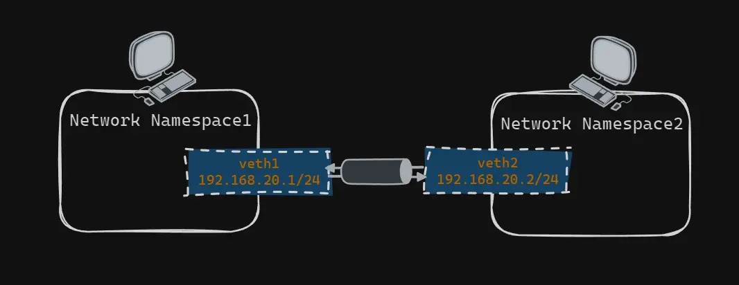
To make two namespaces talk to each other, you can create virtual network devices (such as a veth pair) and assign them to different namespaces. The steps to create and configure the namespaces and get them communicating:
- Create the namespaces with ip netns add.
- Create a veth pair and assign each end to its namespace.
- Inside each namespace, assign IP addresses to the veth devices and bring them up.
- Configure routing tables for routing between the namespaces.
- Use ping to test connectivity between the two namespaces.
Create Network Namespace
Create a network namespace with ip netns add <NAME>.ip netns helpUsage: ip netns list # list all network namespaces ip netns add NAME # create a new network namespace ip netns attach NAME PID # attach a process to a network namespace ip netns set NAME NETNSID # set the namespace ID of a network namespace ip [-all] netns delete [NAME] # delete a network namespace ip netns identify [PID] # identify a network namespace ip netns pids NAME # list the PIDs of processes in a network namespace ip [-all] netns exec [NAME] cmd ... # ⭐ execute a command in a network namespace ip netns monitor ip netns list-id [target-nsid POSITIVE-INT] [nsid POSITIVE-INT]# create network namespacesip netns add ns1ip netns add ns2
Create and Config Veth Pair and
# create the virtual interfacesip link add veth_ns1 type veth peer name veth_ns2ip link set veth_ns1 netns ns1ip link set veth_ns2 netns ns2# check the interfaces inside each network namespaceip --all netns exec ip linknetns: ns21: lo: <LOOPBACK> mtu 65536 qdisc noop state DOWN mode DEFAULT group default qlen 1000 link/loopback 00:00:00:00:00:00 brd 00:00:00:00:00:009: veth_ns2@if10: <BROADCAST,MULTICAST> mtu 1500 qdisc noop state DOWN mode DEFAULT group default qlen 1000 link/ether 36:b6:79:b6:f3:13 brd ff:ff:ff:ff:ff:ff link-netns ns1netns: ns11: lo: <LOOPBACK> mtu 65536 qdisc noop state DOWN mode DEFAULT group default qlen 1000 link/loopback 00:00:00:00:00:00 brd 00:00:00:00:00:0010: veth_ns1@if9: <BROADCAST,MULTICAST> mtu 1500 qdisc noop state DOWN mode DEFAULT group default qlen 1000 link/ether ae:a0:29:4d:6c:7e brd ff:ff:ff:ff:ff:ff link-netns ns2To add an IP address to a network interface on Linux, use ip addr add [ADDRESS]/PREFIXLENGTH dev INTERFACE, then bring the device up.# add IP addresses to the network interfacesip netns exec ns1 ip addr add 192.168.20.1/24 dev veth_ns1ip netns exec ns2 ip addr add 192.168.20.2/21 dev veth_ns2# bring the devices up so they can send and receive packetsip -n ns1 link set veth_ns1 upip -n ns1 link set lo upip -n ns2 link set veth_ns2 upip -n ns2 link set lo up
Config Route Table
ip netns exec ns1 ip route add default via 192.168.20.1 dev veth_ns1ip netns exec ns2 ip route add default via 192.168.20.2 dev veth_ns2ip --all netns exec route -nnetns: ns2Kernel IP routing tableDestination Gateway Genmask Flags Metric Ref Use Iface0.0.0.0 192.168.20.2 0.0.0.0 UG 0 0 0 veth_ns2192.168.16.0 0.0.0.0 255.255.248.0 U 0 0 0 veth_ns2netns: ns1Kernel IP routing tableDestination Gateway Genmask Flags Metric Ref Use Iface0.0.0.0 192.168.20.1 0.0.0.0 UG 0 0 0 veth_ns1192.168.20.0 0.0.0.0 255.255.255.0 U 0 0 0 veth_ns1Ping between Two Network Namespace
With the steps above done, the two network namespaces can now communicate.ip netns exec ns1 ping 192.168.20.2 -c 4PING 192.168.20.2 (192.168.20.2) 56(84) bytes of data.64 bytes from 192.168.20.2: icmp_seq=1 ttl=64 time=0.027 ms64 bytes from 192.168.20.2: icmp_seq=2 ttl=64 time=0.043 ms64 bytes from 192.168.20.2: icmp_seq=3 ttl=64 time=0.062 ms64 bytes from 192.168.20.2: icmp_seq=4 ttl=64 time=0.043 ms--- 192.168.20.2 ping statistics ---4 packets transmitted, 4 received, 0% packet loss, time 3117msrtt min/avg/max/mdev = 0.027/0.043/0.062/0.012 ms
Communicate Using Linux Bridge
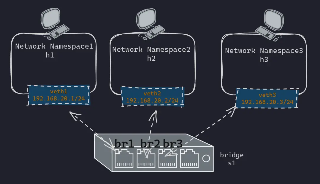
Now that we have seen how network namespaces communicate in the basic case, let’s turn to a scenario closer to real-world use: running multiple network namespaces on the same host. In this situation, keeping the previous approach of wiring namespaces pair by pair becomes very inconvenient.
To simplify this and communicate more efficiently, we introduce a bridge as an intermediary between the namespaces.
Bridge: a network interconnection device that relays at the data link layer, connecting two or more LANs.
Switch: broadly speaking, a switch is any device in a communication system that performs information exchange. The data-link-layer switch discussed here is a switching hub, which is essentially a multi-port bridge.Feature Bridge Switch Number of ports Usually few, e.g. 2 to 16 Many, up to hundreds Forwarding Software-based packet forwarding Hardware-based (ASIC) fast packet forwarding Performance Relatively low High performance, low latency Spanning tree instances Supports only one spanning tree protocol instance Supports multiple spanning tree protocol instances, improving redundancy and efficiency Filtering Basic frame filtering More advanced frame filtering and management Collision domain Usually the whole device is one collision domain Each port can be treated as an independent collision domain Broadcast domain The whole device belongs to one broadcast domain Likewise, but can be split into multiple logical broadcast domains via VLANs VLAN support None or limited Broad VLAN support, can partition multiple logical networks Management Limited management features Rich management features, including configuration, monitoring, and troubleshooting
A Linux bridge not only simplifies the wiring between namespaces, it also provides seamless network communication, letting virtual devices in different namespaces exchange data as if they were attached to the same physical network. With a Linux bridge, we can build a more flexible and scalable virtual network environment.
Here are the steps to connect network namespaces via a bridge:
- Create the namespaces and the bridge with ip netns add.
- Create veth pairs and connect them to the bridge.
- Assign IP addresses to the veth devices and bring them up.
- Test with ping.
Create Network Namespace and Bridge
# create network namespaceip netns add h1ip netns add h2ip netns add h3# create bridgebrctl addbr s1The brctl command comes from bridge-utils
Create Veth Pair and Connect to Bridge
# create veth pairip link add veth1 type veth peer name br1ip link add veth2 type veth peer name br2ip link add veth3 type veth peer name br3# add interface to namespaceip link set veth1 netns h1ip link set veth2 netns h2ip link set veth3 netns h3# add interface to bridge(s1)brctl addif s1 br1brctl addif s1 br2brctl addif s1 br3# checkbrctl showbridge name bridge id STP enabled interfacess1 8000.82fcceb79d4c no br1 br2 br3Config Veth Pair and Bridge
Configure IP addresses and set the state to up.ip -n h1 addr add local 192.168.1.1/24 dev veth1ip -n h2 addr add local 192.168.1.2/24 dev veth2ip -n h3 addr add local 192.168.1.3/24 dev veth3ip link set s1 upip link set br1 upip link set br2 upip link set br3 upip -n h1 link set veth1 upip -n h2 link set veth2 upip -n h3 link set veth3 up
The veth interfaces attached to the bridge usually do not get IP addresses, for the following reasons:
A bridge device (e.g. br0) exists to forward packets; it behaves like a layer-2 switch, working at the link layer. Forwarding on the bridge does not depend on IP addresses; it is based on MAC addresses.
An IP address belongs neither to the NIC nor to the PC itself; it belongs to layer 3 of the OSI protocol stack.
A layer-2 switch works at layer 2 of the OSI model, the data link layer. It focuses on MAC address learning and frame forwarding within a LAN, and does not support routing across networks.
A layer-3 switch combines the functions of a layer-2 switch and a router, working at layer 3 of the OSI model, the network layer. It can perform routing, IP address configuration, and inter-VLAN communication.
Ping
ip netns exec h1 ping 192.168.1.2 -c 2PING 192.168.1.2 (192.168.1.2) 56(84) bytes of data.64 bytes from 192.168.1.2: icmp_seq=1 ttl=64 time=0.076 ms64 bytes from 192.168.1.2: icmp_seq=2 ttl=64 time=0.080 ms--- 192.168.1.2 ping statistics ---2 packets transmitted, 2 received, 0% packet loss, time 1027msrtt min/avg/max/mdev = 0.076/0.078/0.080/0.002 msCommunicate with outside World
Processes inside a container or namespace may need to reach external networks. This is usually done by connecting the container’s network interface to the host’s network interface, or by using network address translation (NAT).