- Database application architecture design
- Different application scenarios call for different database application architectures. They can be classified into single-user, centralized, client/server (C/S), and distributed architectures
- Database structural model design
- Database structural model design generally covers the conceptual, logical, and physical layers, whose design models are the Conceptual Data Model (CDM), Logical Data Model (LDM), and Physical Data Model (PDM) respectively
- Database access method design
- Applications can access the database in several ways, such as direct local interface connections, standard interface connections, and data access layer framework connections
Database Structural Models
- The Conceptual Data Model (CDM) is a user-oriented system data model that describes the conceptual data structure of the real-world system. It lets database designers, at the initial stage of system design, set aside the specific technical concerns of computer systems and the DBMS, and focus on analyzing business data and the relationships among data, describing the system’s data objects and how they are composed.
- The Logical Data Model (LDM) builds on the conceptual data model. From a system design perspective, it describes the composition of the system’s data objects and their associated structures, and considers how these data objects map to the logical representation of database objects.
- The Physical Data Model (PDM) builds on the logical data model and is designed for a specific DBMS. It describes implementation details such as data object organization, storage methods, indexing methods, and access paths of the system data model in the target DBMS.
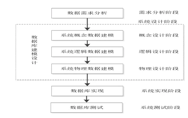
Data requirements analysis stage: gather data forms, reports, queries, business rules, and data update specifications from real business; analyze the system’s data characteristics, data types, and value constraints; describe the system’s data relationships and processing requirements; build the system’s data dictionary
Database design stage: internal database structure design (conceptual, logical, and physical data models); index, view, and query design; table constraint design; trigger and stored procedure design; file organization
Database implementation stage: database creation; writing SQL programs for the data models and physically implementing database objects
Database testing stage: loading production data; system testing of the database
CDM Models the system’s data objects and their relationships from the user’s perspective, helping users analyze the data structure of the information system LDM Models the logical structure of the system’s data objects from the system analyst’s perspective, helping developers analyze the logical data structure of the information system PDM Models the physical storage and structure of the system’s data from the system designer’s perspective, letting the designer concretely define the database table structure of the information system
The E-R Model Method
Basic Elements of the E-R Model
The E-R model is short for “Entity-Relationship Model”. It is an effective method for describing real-world conceptual data models and logical data models.
In the E-R model, the basic elements are entities, attributes, identifiers, and relationships:
- An Entity is a logical-level data abstraction of objective things in the problem domain, such as people, events, objects, and places. It describes the data objects of things, e.g. customers, transactions, products, orders
- An Attribute is a data item that describes a characteristic of an entity. Every entity has one or more attributes
- An Identifier is an attribute (or attributes) that distinguishes different entity instances. An identifier can consist of one or more attributes.
The difference between an identifier and a primary key is that an identifier is a logical concept, while a primary key is a physical concept - A Relationship is an association between entities, such as the link between “student” and “grade”, or between “child” and “father”/“mother”.
The number of entities involved in a relationship is called the degree of the relationship
Entity-Relationship Types
Binary Entity Relationship Types
- One-to-one relationship 1:1
- One-to-many relationship 1:N
- Many-to-many relationship M:N
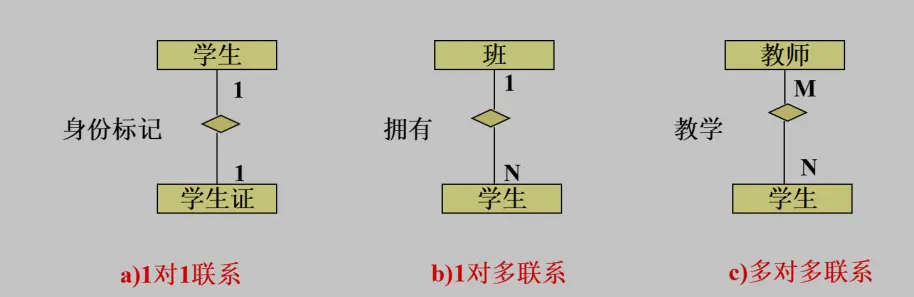
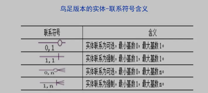
The relationships above reflect how many instances of one entity correspond to instances of another. The term Cardinality denotes the number of instances in an entity relationship. Besides the quantitative correspondence, sometimes we also need to express whether an entity’s participation in the relationship is necessary, that is, optional or mandatory
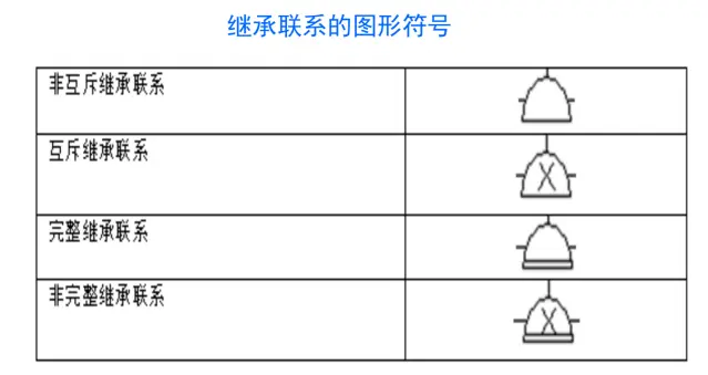
Inheritance Relationships
In the E-R model, besides basic relationships, there are also inheritance relationships between entities. An inheritance relationship expresses similarity between entities. In an entity inheritance relationship, one end is the entity holding the common attributes, called the parent entity; the other end is one or more entities that share similar attributes with the parent but also have their own specifics, called child entities.
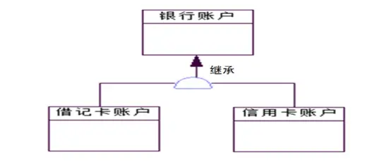
Inheritance relationships can further be divided into:
- Mutually Exclusive Inheritance Relationship: in this type of inheritance, a child can inherit from only one parent, not from multiple parents at the same time
- Non-Mutually Exclusive Inheritance Relationship: in this type of inheritance, a child can inherit from multiple parents, that is, one child may belong to several parents
- Total Inheritance Relationship: in this kind of inheritance, every instance of the parent entity must be an instance of one or more child entities. In other words, every instance in the parent entity must have a counterpart in the child entities. For example, if we have a “Person” entity with two child entities, “Student” and “Teacher”, then under total inheritance every “Person” must be either a “Student” or a “Teacher”.
- Partial Inheritance Relationship: in this type of inheritance, an instance of the parent may belong to none of its children; in the example above, partial inheritance allows some “Person” instances that are neither “Student” nor “Teacher”.
Strong and Weak Entity Relationships
In the E-R model, entities can be classified by their semantic relationships into Weak Entities and Strong Entities. A weak entity is one that depends on another entity, that is, its existence presupposes the existence of the other entity. The entity being depended on is called a strong entity. For example, in the relationship between a school and its students, the student is the weak entity and the school is the strong entity.
- Strong Entity
- Weak Entity
- Identifier Dependent Weak Entity
If the weak entity’s identifier contains the strong entity’s identifier, the weak entity is called an identifier dependent weak entity - Non-Identifier Dependent Weak Entity
If the weak entity’s identifier does not contain the strong entity’s identifier, the weak entity is called a non-identifier dependent weak entity
- Identifier Dependent Weak Entity
Database Modeling and Design
Conceptual data model design is the process of extracting, classifying, aggregating, and generalizing data entities from the real world to build a structure that reflects the composition of the system’s business data.
Steps
- Analyze business data and extract data entities
- Define entity attributes and their identifiers
- Establish entity relationships and build local E-R diagrams
- Classify, aggregate, and generalize the partial E-R diagrams
- Refine the global E-R diagram and establish the composition of the system’s business data
Data Model (DM) element correspondence tableCDM LDM PDM Entity Entity Table Attribute Attribute Column Identifier Primary Identifier/Foreign Identifer Primary Key/Foreign Key Relationship Relationship Reference (referential integrity constraint)
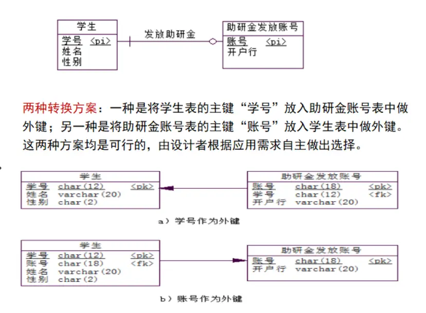
1:1
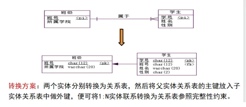
1:N
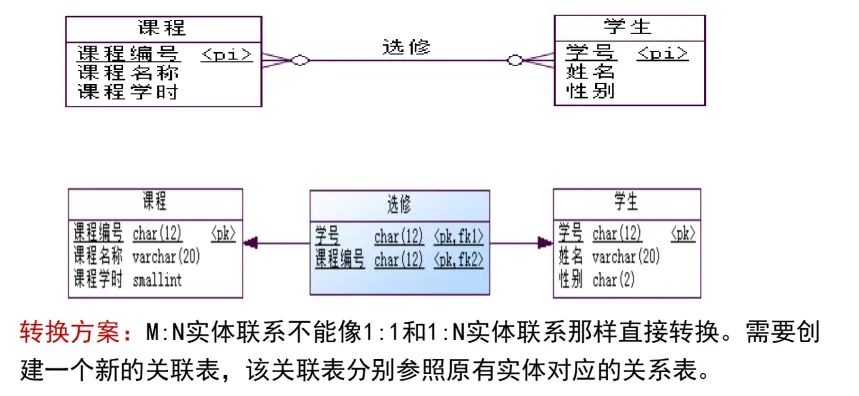
M:N
Normalized Design
Why do we need normalized database design?
- Reduce redundant data in the database, keeping each piece of data stored only once as far as possible, which effectively lowers the effort of maintaining data consistency.
- Design sensible inter-table dependencies and constraints, making it easier to enforce data integrity and consistency.
- Design a sound database structure, making it easier for the system to access and process data efficiently.
Functional Dependency
Definition: given a relation schema R(U), where U is the attribute set of relation R, and X and Y are subsets of U. Let t and s be any two tuples in relation R. If t[X] = s[X] implies t[Y] = s[Y], then Y is functionally dependent on X, written X→Y.
The left side of a functional dependency is called the determinant, the right side the dependent. Both the determinant and the dependent are sets of attributes.
Suppose we have a relation schema
Rrepresenting a student enrollment system, whereU, the attribute set ofR, is{StudentID, Name, CourseID, CourseName, Teacher}
For any two tuplestands, for example
Tuplet: {StudentID: 001, Name: "Xiaoming", CourseID: C101, CourseName: "Math", Teacher: "Mr. Li"}
Tuples: {StudentID: 001, Name: "Xiaoming", CourseID: C102, CourseName: "English", Teacher: "Mr. Wang"}
we always havet[StudentID] = s[StudentID] implies t[Name] = s[Name]
So StudentID determines Name, that is,StudentID→Name
Types of functional dependency:
- Total Functional Dependency
IfX→Y, and for every proper subsetX'ofX,X'→Ydoes not hold, thenX→Yis a total functional dependency - Partial Functional Dependency
IfX→Y, and there exists a proper subsetX'ofXsuch thatX'→Y, thenX→Yis a partial functional dependency - Transitive Dependency
IfX→YandY→Zhold, thenX→Zholds, which is called a transitive dependency - Multivalued Dependency
Let U be the attribute set of relation schema R, X and Y subsets of U,Z=U-X-Y, and letxyzdenote values of the attribute sets XYZ. For a relation r of R, if whenever the tuples(x, y1, z1)and(x, y2, z2)exist in r, the tuples(x, y1, z2)and(x, y2, z1)also exist, then a multivalued dependency holds on schema R.(Data Structures, Mr. Li, “Data Structures and Algorithms - Beginner”)
(Data Structures, Mr. Wang, “Data Structures and Algorithms - Advanced”)(Data Structures, Mr. Li, “Data Structures and Algorithms - Advanced”)
(Data Structures, Mr. Wang, “Data Structures and Algorithms - Beginner”)
Relational Normal Forms
Relational normalization is the process of decomposing a relation with access anomalies into well-structured relations, so that these relations have minimal or no redundancy.
A Normal Form (NF) is a schema in which a relational table meets a particular degree of normalization.
- First Normal Form (1NF)
If the attributes in a relational table cannot be subdivided further, the relation satisfies 1NF. Otherwise, the table is not a relational table.If “contact information” is an attribute of a relational table, it can still be subdivided into attributes like phone number and email; eliminating such attributes and splitting contact information into phone number, email, etc. satisfies 1NF.
- Second Normal Form (2NF)
If a relation satisfies 1NF and eliminates partial functional dependencies among its attributes, it satisfies 2NF. Given a relation(A,B,N,O,P)with composite primary key(A,B), if none of the three non-key attributesN,O,Pdepends on only A or only B, the relation satisfies 2NF; otherwise it does not.We have a relation schema R whose attribute set U is {StudentID, CourseID, StudentName, CourseName, Teacher}, with composite primary key (StudentID, CourseID). But StudentName depends only on StudentID, while CourseName and Teacher depend only on CourseID, so there are partial functional dependencies and the relation does not satisfy 2NF.
- Third Normal Form (3NF)
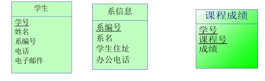
If a relation satisfies 2NF and cuts off transitive functional dependencies among its attributes, it satisfies 3NF.{StudentID, Name, Department, Address (dorm address), Phone, Email}: StudentID determines Department, and Department determines the dorm address, so StudentID determines the dorm address. A transitive dependency exists and 3NF is not satisfied; the student relation can be further decomposed into student and department tables
- Boyce-Codd Normal Form (BCNF)
If every determinant of every functional dependency in a relation is a candidate key, the relation satisfies BCNF - Fourth Normal Form (4NF)
If a relation satisfies BCNF and eliminates multivalued dependencies, it satisfies 4NF.
Denormalization
Denormalization means appropriately relaxing normal form constraints: instead of requiring a relational table to reach a very high degree of normalization, some data redundancy is allowed in exchange for data access performance.
Basic denormalization techniques:
(1) Add redundant or derived columns
(2) Merge multiple relational tables into one